For this challenge, we are provided with both encrypted hex to load on the rhme2 board and an unencrypted binary dump that we can run on an emulator or a real Arduino.
[Disclaimer]: Always remember to RTFD!
0x00 -- intro
Furthermore, if we have access to a debugWire compatible board (as I did), like the AVR Dragon we can debug the device using the on chip debugger. Debugging Arduino boards is somewhat tricky as for this specific AVR chip JTAG is not supported, but a proprietary debug protocol called debugWire is instead.
This protocol runs on one single wire (hence the name!) but turns out that the wire happens to be the RESET line, which kind of interferes with how the Arduino is manufactured... Long story short, the reset line from the microcontroller is connected to the usb controller RTS and DTR (to provide easy user programming though the Arduino IDE), to 5V through a 10K pull-up resistor and finally to the ISP and external pin headers and,... just too much stuff to have a reliable signal carrying the debug info back and forth and it may be necessary to cut a trace or apply some (de)soldering skills.
You can find detailed instructions here. Fortunately, I had a modified Arduino UNO that was debug-enabled, so I only needed to cut the trace.
I used radare2 for static reverse engineering and Atmel Studio with AVR Dragon and a modified Arduino UNO for debugging.
0x01 -- readSerial() and the USART
The program asks for input, checks it, and displays 'Better luck next time!' on failure. To understand this, we need to examine the USART (Universal Synchronous and Asynchronous serial Receiver and Transmitter) architecture of the microcontroller.
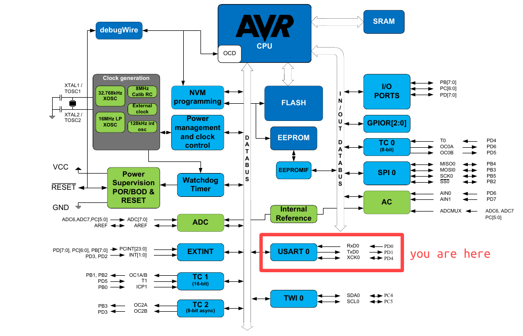
The USART (Universal Synchronous and Asynchronous serial Receiver and Transmitter) is just a peripheral connected to the system data bus and in order to interact with it we just load and retrieve data from I/O registers.
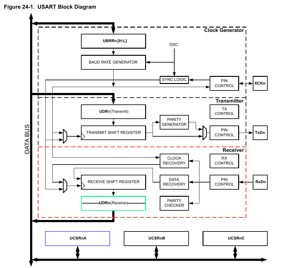
After reading several pages of datasheet fun about how USART does work it seems clear that we need to keep track of at least two things:
Receive Complete (RXC) Flagon the UCSRnA Register [Offset: 0xC0]: This flag bit is set when there are unread data in the receive buffer and cleared when the receive buffer is empty (i.e., does not contain any unread data).USART I/O Data Register 0[Offset: 0xC6]: Reading the UDR0 Register location will return the contents of the Receive Data Buffer Register (RXB).
That's enough theory! We then need to find a loop-like structure checking against 0xC0 I/O register. Opening the binary file with r2 and after a few moments of crawling, searching and renaming it yields:
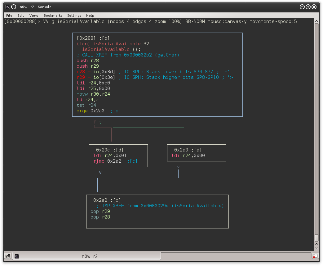
We found a function which loads the contents of the 0x00C0 I/O register (using Z as a pointer because ld r24,z does r24 ← (Z): it sets r24 to 0x00 in case we have data in the buffer. We also may have noticed the XREF to this function from 0x02b2:

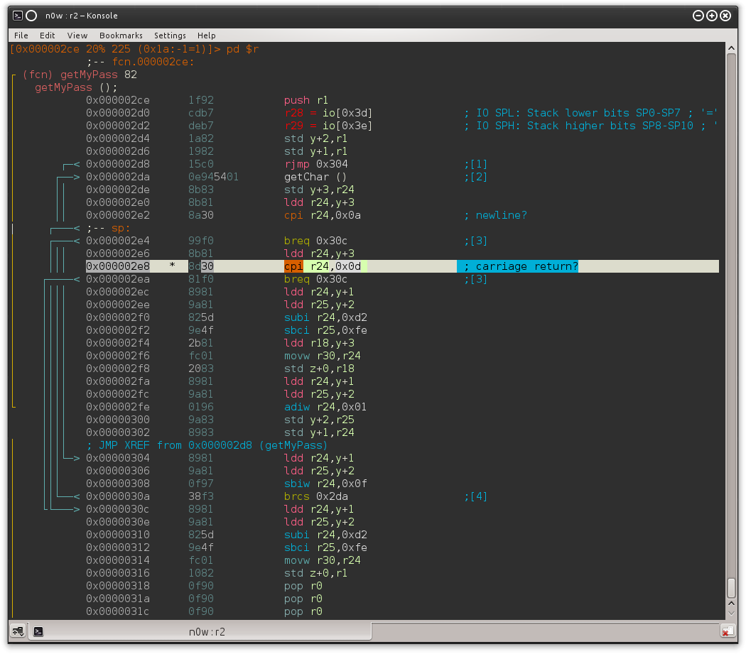
And following the XREF from 0x2a8 we end up in another function (I called it getMyPass) which loops until 0x0D or 0x0A is received (that is, \r or \n, ending the string).
0x02 -- debug
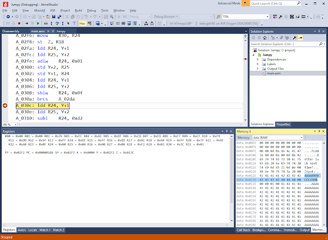
Now let's go to Atmel Studio and set a BP on 0x0000030c; that's where it will jump when a 0x0d it's received.
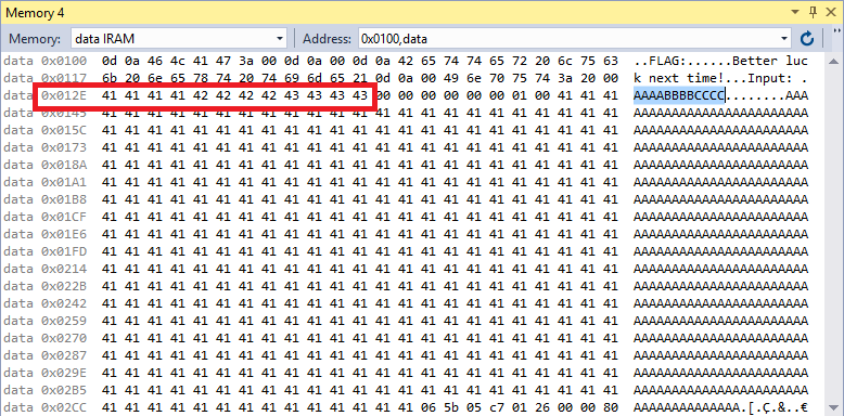
The array containing our password starts at a fixed memory location: 0x012E.
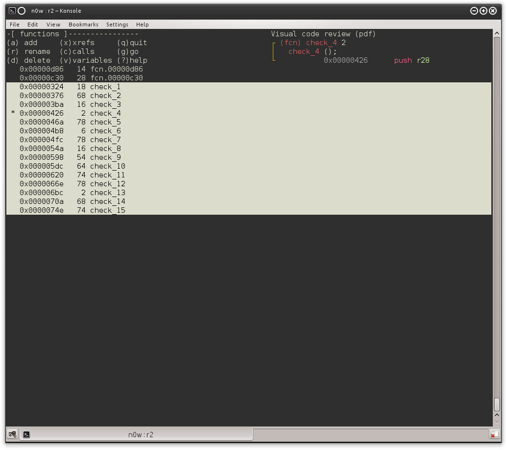
From there it goes jumping (surprise!) between functions. Back to r2 then, and after several hours of AVR assembly digging we start to see a pattern: from 0x00000324 to 0x0000074e there are several functions defined (push r28, push 29... [stuff] ... pop r29, pop 28, ret) and each one of them seems to perform simple math operations on some of our password characters (i.e. fixed memory locations) as follows:
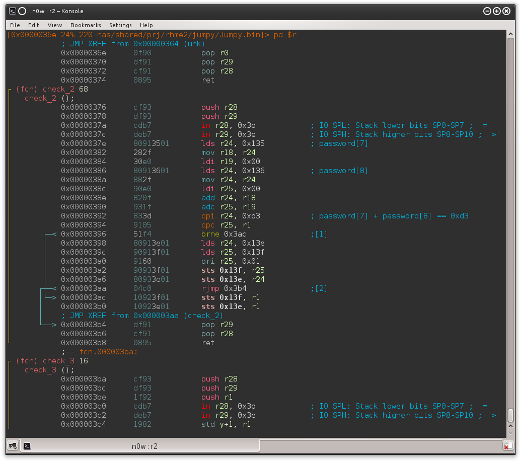
Take a look at the comments for clarity; the check_2 function just retrieves the values of password[7] and password[8] (that is, 0x135 = <base>0x12E + <offset>7), adds them together and checks if the result equals 0xD3. If the branch is taken (brne) the runtime flag generation code does not get executed. This pattern gets repeated 12 times more, checking against a different constraint each time.
0x03 -- re
Every function matching the pattern above was renamed as check_
The actual execution order is the following:
check_1 → check_2 → check_13 → check_11 → check_12 → check_6 → check_8 → check_14 → check_4 →check_9 → check_7 → check_3 → check_5 → check_10 → check_15
And a brief description of every check:
- check_1: Computes entered password length.
- check_2:
password[7] + password[8] == 0xD3 - check_3:
password[12] * len(password) == 0x297 - check_4:
password[9] + password[10] == 0x8F - check_5:
password[4] * password[5] == 0x122F - check_6:
password[3] + password[4] == 0x92 - check_7:
password[10] * password[11] == 0x2873 - check_8:
password[6] * password[7] == 0x2B0C - check_9:
password[1] + password[2] == 0xA7 - check_10:
password[10] + password[12] == 0xA0 - check_11:
password[0] * password[1] == 0x13B7 - check_12:
password[2] * password[3] == 0x1782 - check_13:
password[8] * password[9] == 0x15C0 - check_14:
password[5] + password[6] == 0xA5 - check_15: Checks if every earlier step was taken properly.
At first I tried to solve it with pen and paper, but my head almost blew up from such hardcore math and ended up writing a python script:
password = {}
password[0] = 0x67

for i in range(13):
    for z in range(256):
        #print ("## --- Current: {} --#".format(z))

        if z == 0 or z == 10 or z == 13:
            continue
        else:
            current = struct.pack("B", z)

        if i == 0:
            if password[i] * z == 0x13B7:
                password[i+1] = z

        elif i == 1:
            if password[i] + z == 0xA7:
                password[i+1] = z

        elif i == 2:
            if password[i] * z == 0x1782:
                password[i+1] = z

        elif i == 3:
            if password[i] + z == 0x92:
                password[i+1] = z

        elif i == 4:
            if password[i] * z == 0x122F:
                password[i+1] = z

        elif i == 5:
            if password[i] + z == 0xA5:
                password[i+1] = z

        elif i == 6:
            if password[i] * z == 0x2B0C:
                password[i+1] = z

        elif i == 7:
            if password[i] + z == 0xD3:
                password[i+1] = z

        elif i == 8:
            if password[i] * z == 0x15C0:
                password[i+1] = z

        elif i == 9:
            if password[i] + z == 0x8F:
                password[i+1] = z

        elif i == 10:
            if 13 * z == 0x297:
                password[12] = z

        elif i == 11:
            if password[12] + z == 0xA0:
                password[i] = z
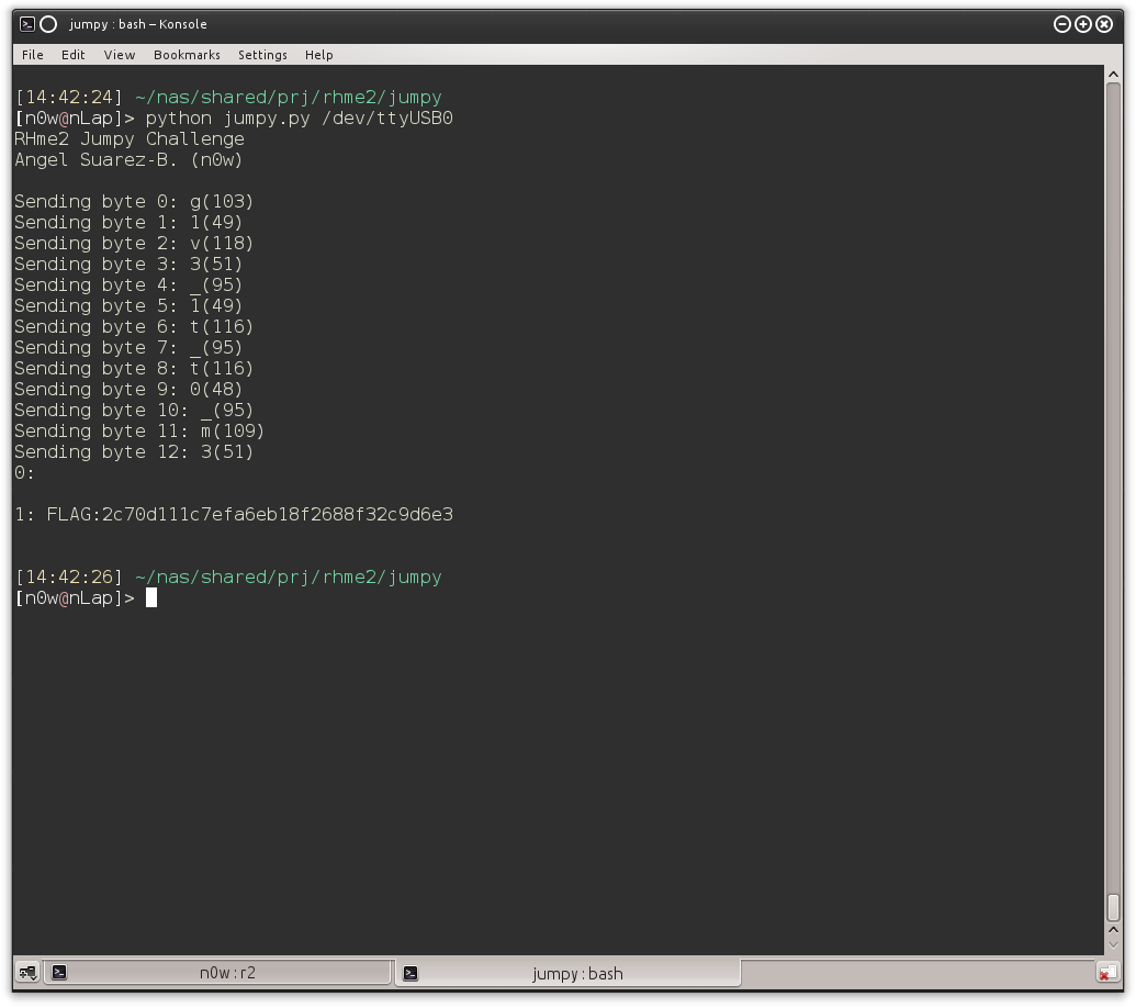
The password turned out to be g1v3_1t_t0_m3 yeah! :D
So that was it! It was really fun and I did learned a lot of AVR internals!